Client:
DBB, RTA
DBB, RTA link opens in a new tab
Sheikh Rashid Bin Saeed Roads Improvement Corridor
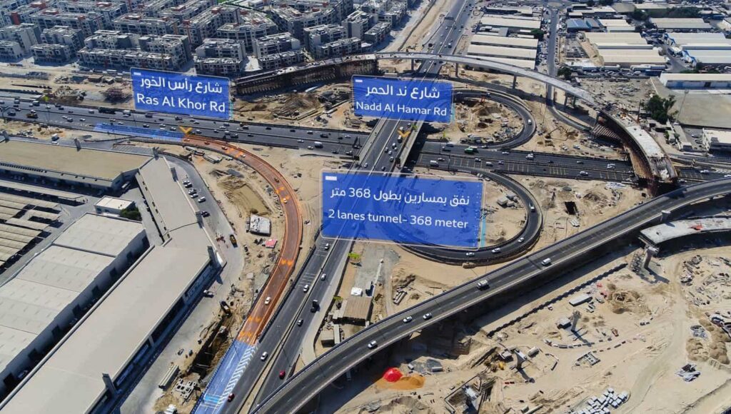
Sheikh Rashid Bin Saeed Roads Improvement Corridor, which extends 8km along Ras Al Khor Road, runs from the intersection of the Dubai-Al Ain Road to the junction of Sheikh Mohammed bin Zayed Road.
It is one of the biggest improvement projects handled by RTA at the moment.
The improvement of the corridor involves widening Ras Al Khor Road from three to four lanes in each direction and constructing a two-lane service road to ease the traffic flow.
The project also includes improving the intersection of Nad Al Hamar Road with Ras Al Khor Road.
Soil nail wall monitoring at Nad Al Hamar level
The widening of Ras Al Khor Road, at Nad Al Hamar interchange level, means the modular blocks around the existing bridge abutment had to be removed. In order to ensure the stability
of the abutment, soil nails were chosen, before an RCC retaining wall could be cast.
In order to assess and verify the stability of the anchoring solution on such a critical road axis, the set-up of an instrumentation and automatic monitoring system was imposed.
Sixense was contracted by DBB to carry out the instrumentation and the subsequent automatic monitoring of the soil nail walls, on both sides of the road. A monitoring system was implemented on site using 1 Automatic Total Station (ATS) installed on the median strip, to provide a comprehensive 24/7 survey of the optical prisms installed on several vertical sections
of the wall.
On this project, Sixense and its partner GTC decided to mutualize their skills and work together, providing not only the instrumentation recommendations and the actual monitoring, but also advising the tolerable expected movements of the structure, and the different automatic alarm levels.
Images of the project
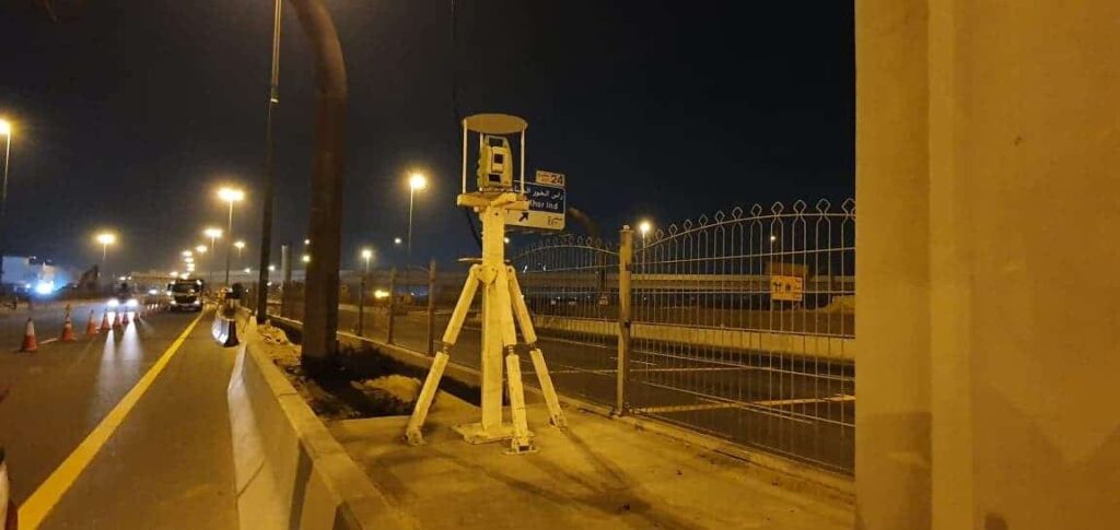
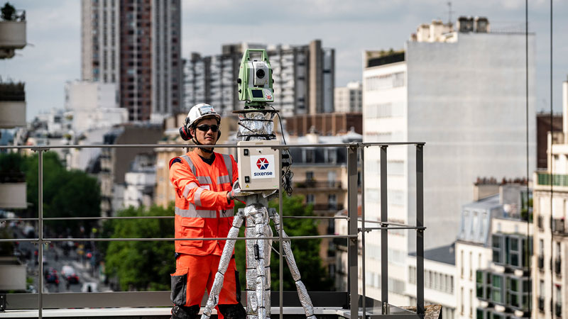
Automatic Total Station (ATS)
Optical prisms